Hello and Welcome!

Hello and Welcome!

My name is John Nicholl. I'm an Industrial Design student, based in Adelaide, South Australia and this is the beginning of somewhere that I can think aloud and share my work.

This blog is somewhat outdated.
More current projects are posted on my website.

Twitter, Instagram and Tumblr: jwrnicholl

Monday, March 31, 2014

Computer Modelling Journal, Week 4

I am currently working on the arms piece. There's a lot of consider when trying to understand the shape. I am being encouraged to avoid doing lofts and then just adding a radius to round the corners, except that from what I can tell, that is actually what the shape is. There its almost like there's an 8th of a sphere at the shoulder, then it rounds off and flattens out down to the elbow and is just a little tube from there on. I don't understand why I should be making it more complicated that it already is. Its not like a sports car where the shapes are supposed to look sleek and organic, this is a mini-figure's arm. So far I'm working with this...


I took an old Lego piece and cut the joint off its shoulder to get a nice close up scan to draw some construction over.


Sick of arms...

Monday, March 24, 2014

Computer Modelling Journal, Week 3

Why does Solidworks have to show me error messages every time there is something to complain about? There should be errors displayed in a news feed style in the corner of the screen so that I can see when they occur, then address them accordingly. No, I do not want  to use the wizard to solve the problem... It doesn't work. I do not want to have to deal with all your popup prompts each time I rebuild the model which I'm troubleshooting. I'll fix it when i fix it!

Problems this week...

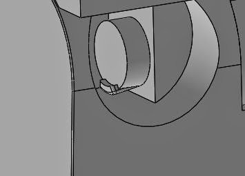
There is a lip overhanging there which I need to pull back... (Left) But that won't happen till i figure out why the holes in teh back of the Lego mini-figure's leg is not being centered and causing that tiny blip. (Right)


Good news is that it looks pretty sweet so far. I've made a little block for it to stand on so that i can get some good measurement and alight the pieces and features to accurately fit onto a real Lego brick. Also, mirroring the leg piece was such a sleek process. I don't like having to rebuild the sketch as i make adjustments though.


I also made the head... I like this one.


Things left to do are the arms and hands. I don't feel like they will take as long because they don't connect to and Lego bricks. At the moment I'm still not sure what accessory I want to make for the mini-figure. Not to fear though... it can't be that hard, no matter what I decide to do.


Monday, March 17, 2014

Computer Modelling Journal, Week 2

This week I have been working on the Lego person model. The end goal is to have full technical drawings for all the parts of the Lego person.

 I started with the head, mainly because it has the least complex shape. I went and bought a new Lego person from the shops so that I could have a little comparison between the Lego I already had at home. The head pieces have no longer got a hole in the top, which is kinda confusing. Isn't that a choking hazard?

As for the body, there is a hell of a lot of detail. They've gotten smarter about how they Lego's internal structure works. There's more emphasis on supporting ridges instead of just having thicker walls. There's a small area just inside the sides of the piece for the legs to slide into, as well as all the crazy convoluted support structures for making sure the pieces clip together properly. I've made sure to take careful note of any small details, especially around the arm sockets and the area that holds the legs. So far, this is what I've got in term of the model. I'm thinking I'll scan the Lego's decals and add them into the model, then do a comparison between the two.

 Maybe I should get another Lego person and cut it open to get more detail....


After spending a good 10 minutes jotting down some measurements from the legs, I realised that the sizing of the bottom of the foot is dictated by the spacing of the Lego brick's notches. The legs also have a slight angle on their outer side. There's so much more detail that you would care to consider at a glance. So far I've modeled the leg, but I'm still unsure about the spacing and how it will go together with the hips. There's also the question about weather or no I'm happy with the way I've hollowed out the top section. It's not only a difficult and unusual shape in there, I'm not sure I fully understand it either. (Below Middle)


This week I've been abusing the "Convert Entities" tool to project geometry through to the face I'm working on. In Solidworks it took a little bit of tinkering to figure out how to do it, but eventually I got there. Also I had some trouble with trying to mirror a feature but then not being able to merge the body after I'd finished with the mirror tool. The work-around was to just go back and mirror the sketch I'd done a bunch more times to get the detailing inside the body part done. For all the parts I went with ABS Plastic (which is what Lego is made from) and a white mild gloss finish.

Next week should be the arm and hand pieces. I'm not looking forward to the awkward angles and trying to measure them with the vernier calipers. I might touch on the hips too.

Monday, March 10, 2014

Computer Modelling Journal, Week 1

This will be the first of many entries with regards to computer modelling for product design. Over the course of the next half year, i'll be recording any problems, triumphs or anything that's worth documenting regarding the process and experiences I come across while completing assignments. The software package I'll be using is Solidworks 2013. Hopefully there will be more pictures than words.

Once being given the technical Drawing for the bottle, It became clear that there wer some details that would be hard to see without a electronic copy to zoom in on. In particular the top of the bottle and teh base where the knurled feature is.

The top left image out of the following shows a small flat ridge after the first fillet from the bottle's top. Without it, the sketch is impossible to constrain. Also there is a detail where two concentric arcs are required to find a point of intersection which constrains the centre point of the arc just below that small flat ridge.

The top right image just explains the flat surface just before the very bottom of the bottle's upper section.

This bottom image was a little confusing because it leaves a lot to the imagination to try understand the shape of the 3D feature that is is trying to describe. With whats shown here, I presumed it is half of a football shape.
The sketches looked pretty alright to me afterwards.


The final Product after a quick render...


This is the first part of the assignment done. Next to come is a little CAD Lego person and a 3D printed item for it to carry or be attached to. I'd thought of making a tiny Mech for it to sit in, but that might be a bit too big of a project for the time frame I've got. Maybe just robotic pants will suffice.

Sunday, December 29, 2013

End of a Year

Although there hasn't been much productivity since Uni ended for the year, there are the best of what was in my folio that i submitted. These are more or less in the order that I drew them.

Shiny Cube!
First full attempt at rendering shiny coloured objects.

Camaro
This one was purely a render job. The underlay was not my own work.

Chrome Camaro
Same as above.

Padlock
Chrome tube rendering practice. Thought it might out some key scratches on the body of the lock just for fun. I've not got the curve on the embossed rectangle right, but i'll live with it.

Hand Mixer
Redesigned hand mixer. Entirely my own. This one is my favorite in terms of side profile drawings.

Dust Buster
Drawn from a set of elevation views that were provided to me. Favorite perspective drawing.


Hot Glue Gun
Side profile from an existing design. the base of colour was done with pastel and lighter fuel. Fun times.

Bug Robot
I had a lot of fun with this one. really wanted to make the weapon thing look a little more like it was glowing. It could probably use a rear angle view to explain the shape further.

Sunday, October 20, 2013

Cardboard!

…and I’m back!

It’s been a while since the last post. Partly, due to laziness and partly due to the lack of interesting content to actually post. There was a short break from Uni and then I had an incident on my way home from Uni on my bicycle. My second ring finger got squished so hard that the bone at the very tip forces its way through my skin and found itself sitting just outside the stop where the last joint is. I took some gruesome photos of it that won’t post here. Moving on through to what my last project was!

A cardboard chair! The task was to take a large sheet of cardboard, pre-determined in size, and made a char out of it that could support 80kg. The rules were simple, nothing but cardboard. No staples, tape or any other foreign fasteners… only cardboard. It’s definitely not something that hasn’t been done before, and done to death I don’t doubt.

I tried to focus on making the chair with as fewer separate pieces as possible to try and draw out as much strength in the material as possible. The result was two main parts, a seat and a backing, with a number of tiny fasteners to keep the whole thing together.


The Hexagon shape was inspired by an origami flower that I’d looked up while trying to figure out the best way to fold the cardboard. I folded one up out of paper and it seemed to be really strong, especially considering it was only made from paper at this point. There were way too many fold to make it out of the cardboard, so instead I came out with a simpler shape with less folds.

The back followed through just as something that I thought would be easy to slap on it and everything would be fine. How wrong I was. The back needed almost just as much strength in it as the seat. This is where it falls short of being a viable chair solution. For a first effort, I’m satisfied.


Thursday, September 19, 2013

Hardwood Box

If you are a fan of timber craft, this is for you.

Back in my final year of high school I took small furniture construction as one of my subjects, which was awesome. This is the first assessment task that I built. It is a small timber box, which has the assassin's creed symbol stained into the lid.

The dark timber is Jarrah and the light timber is Meranti. Its held together with dovetails on the corners and has a rather large heavy lid. From memory, the lid is actually 22mm thick Meranti with the Jarrah border around it. Currently it serves as a box to hold my shot glasses and cocktail shaker.

Working with timber is such a pleasure to me and the natural grains of timber almost do the work for you as far as surface appearance goes.

I thought this would be a longer post... oh well...

This is the final project form high school!

A TIMBER SAFE! The amount of people that tell me how it is not secure because it could just be torn apart with a chainsaw is borderline annoying. This one has a She-oak door, Meranti sides, Jarrah handle, jarrah corners, Rosewood border and Rosewood edge trimming. The corner would have to be the best part, where the timber was cut and position so that all sides of the safe show only end grain. Also... there is a small piece of cypress pine inside the door where I drilled a hole for a hinge, but then found that I'd need two hinges. There was just a small piece of it laying around so we used it as a plug.

The original plan was to build the locking mechanism out of brass, but i was young a naive back then and didn’t understand the exact science behind a combination lock. Since I finished school I rebuilt the lock, using a modified door lock from a hardware store... but here’s a picture of the old combination lock face.