New Project!!
Modelling the Logitech M185 Wireless Mouse.
Looking at the mouse, its got a really organic shape. It'd going to take a lot more effort that the previous project. The focus is to learn how to use Solidworks' "Surface" tools which apparently make modelling these fluid shapes much easier.
Before getting into too much detail, there are three parts that can just pull apart on the mouse, excluding the battery. Mouse, Bottom cover and USB Receiver. I'll be modelling the receiver also.
Here's the breakdown into the three main assemblies that will exist. There's the Base and Top sections. The top consists of the two left most parts, and the bottom on the right. Within these there are smaller parts... like the scroll wheel mechanism in the top and the electronics in the bottom. I'll probably end up with some sub-assemblies in the larger bottom part.
Until I've had a chance to learn more about using those tools, I'm going to focus on the parts which i can model easily and save myself time further down the track. So that means i'll start with the scroll wheel and the spring that makes it click. Quite a simple mechanism inside. It'd be interesting to see the workings of the Logitech mice which have the "Hyper-Fast Scrolling" feature which allows switching between standard clicking and a freely spinning wheel.
There will be three parts to the mechanism that I can make right now... but the larger middle section of the mouse will have to wait. There some heavy stuff going on there. You haven't seen the underside of it yet. The frustrating part of this project is that making the mouse from scratch with a self created design in mind would be simple enough, but trying to derive dimensions from an organic shape like it is will be difficult. I've considered encasing the whole mouse in a resin and then cutting it into sections with a band saw... but I'm not sure if it will get clear enough information to work with, especially if i don't know how far from the edges of the mouse I actually am. A clear resin might do the trick though. Oops, tangent.
Took to the wheel and spring with the vernier calipers and pulled out the dimensions I need. Hopefully I didn't forget any because I'd rather not have to pull it off again. Don't know if i can get it back on yet.
So I've forgotten to measure the inside of the rubber part, and subsequently the thickness of the outer ring of the inner part of the wheel. 14.7 mm on the inside of the plastic innards and 15 on its outside. Therefore 15 also for the rubber.
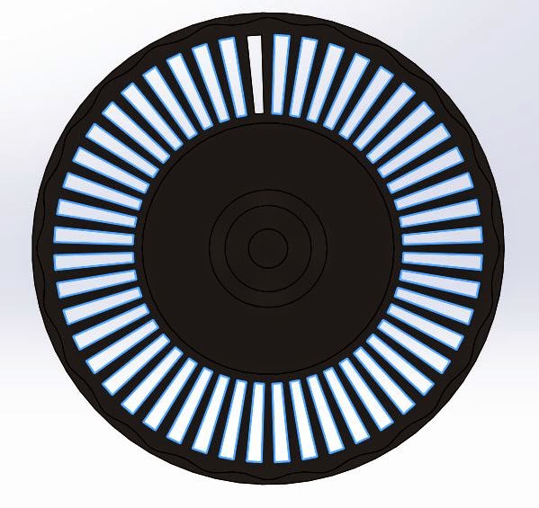
The basic approach was to make the inner section of the wheel first. Pretty simple with a revolve from a sketch with all the necessary dimensions. I noticed there was some additional thickness in a rippling form on the inside of the wheel, so I added that in before cutting away the holes to make the botches which cause that awesome click sound when you scroll.
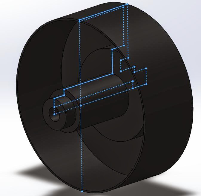
Making the rubber outside of the wheel probably could have been approached differently, but what I've got looks pretty accurate to me. First came a revolve with a parabola. Then a boundary cut between a sketch on a plane above the wheel and another on the front plane. Repeating the same cut gave the other half of the groove. (Errors occurred with a mirror feature) Finally, a 1 mm fillet finished the wheel.
Smack the two together in an assembly, and there it is.
Hello and Welcome!
Hello and Welcome!
My name is John Nicholl. I'm an Industrial Design student, based in Adelaide, South Australia and this is the beginning of somewhere that I can think aloud and share my work.
More current projects are posted on my website.
Twitter, Instagram and Tumblr: jwrnicholl
Showing posts with label Plastic. Show all posts
Tuesday, April 8, 2014
Friday, April 4, 2014
Computer Modelling Journal, Week 5
The last week! I've just submitted my work online and I've got nothing left to do but go to the pub. WOO
Not the usual day for a post but I need to update what I've been doing for this last couple days. The basic gist of what I've done is the Arm and Hand parts.
Initially the arm was giving me some grief. I can't say its perfect, but frankly I'm sick of it and the fact that I'm just re-creating something that already exists, I'm not fussed. Its close enough! I had a few problems with trying to get the arm to have that strait edge on what would be the inside. (the part that touches the body) If you look at the post from last week, you'll see the line I'm talking about. Attempt 1 (left) and Attempt 2 (right) are alright... but the final shape I went with is a little bit less awkward. (bottom) The line at the bottom of the flat face there comes about as a result of an extrusion from the front face where the hand goes. I'd like to have made it a little different but I kept getting one of those really vague errors that Solidworks loves to give. So i found a workaround with a slightly modified sketch.
Not the usual day for a post but I need to update what I've been doing for this last couple days. The basic gist of what I've done is the Arm and Hand parts.
Initially the arm was giving me some grief. I can't say its perfect, but frankly I'm sick of it and the fact that I'm just re-creating something that already exists, I'm not fussed. Its close enough! I had a few problems with trying to get the arm to have that strait edge on what would be the inside. (the part that touches the body) If you look at the post from last week, you'll see the line I'm talking about. Attempt 1 (left) and Attempt 2 (right) are alright... but the final shape I went with is a little bit less awkward. (bottom) The line at the bottom of the flat face there comes about as a result of an extrusion from the front face where the hand goes. I'd like to have made it a little different but I kept getting one of those really vague errors that Solidworks loves to give. So i found a workaround with a slightly modified sketch.
I have to say my favorite part was the hand. It really has a lot of detail, and the shape is awesome but without being too complex. Basically I just went through with a revolve at an angle to make the stick, then extruded the hand shape from the Top Plane.
Part of the assignment was also to build an accessory. I went with a cape. Following the same concept as a backpack and the bear accessories, it clips in under the head on the neck piece of the body. The bulk of the detail is an absurd spline sketch at the bottom of the cape, which is lofted up along some guidelines to where it attaches to the mini-figure. The bottom also uses a spline, but this time a lofted cut which just takes away that boring bottom edge I'd have ended up with without it.
Finally... This is what the whole Lego Mini-figure looks like!
Labels:
ABS,
Arm,
industrial design,
Journal,
Lego,
Plastic,
Solidworks,
student
Monday, March 17, 2014
Computer Modelling Journal, Week 2
This week I have been working on the Lego person model. The end goal is to have full technical drawings for all the parts of the Lego person.
I started with the head, mainly because it has the least complex shape. I went and bought a new Lego person from the shops so that I could have a little comparison between the Lego I already had at home. The head pieces have no longer got a hole in the top, which is kinda confusing. Isn't that a choking hazard?
As for the body, there is a hell of a lot of detail. They've gotten smarter about how they Lego's internal structure works. There's more emphasis on supporting ridges instead of just having thicker walls. There's a small area just inside the sides of the piece for the legs to slide into, as well as all the crazy convoluted support structures for making sure the pieces clip together properly. I've made sure to take careful note of any small details, especially around the arm sockets and the area that holds the legs. So far, this is what I've got in term of the model. I'm thinking I'll scan the Lego's decals and add them into the model, then do a comparison between the two.
Maybe I should get another Lego person and cut it open to get more detail....
After spending a good 10 minutes jotting down some measurements from the legs, I realised that the sizing of the bottom of the foot is dictated by the spacing of the Lego brick's notches. The legs also have a slight angle on their outer side. There's so much more detail that you would care to consider at a glance. So far I've modeled the leg, but I'm still unsure about the spacing and how it will go together with the hips. There's also the question about weather or no I'm happy with the way I've hollowed out the top section. It's not only a difficult and unusual shape in there, I'm not sure I fully understand it either. (Below Middle)
This week I've been abusing the "Convert Entities" tool to project geometry through to the face I'm working on. In Solidworks it took a little bit of tinkering to figure out how to do it, but eventually I got there. Also I had some trouble with trying to mirror a feature but then not being able to merge the body after I'd finished with the mirror tool. The work-around was to just go back and mirror the sketch I'd done a bunch more times to get the detailing inside the body part done. For all the parts I went with ABS Plastic (which is what Lego is made from) and a white mild gloss finish.
Next week should be the arm and hand pieces. I'm not looking forward to the awkward angles and trying to measure them with the vernier calipers. I might touch on the hips too.
I started with the head, mainly because it has the least complex shape. I went and bought a new Lego person from the shops so that I could have a little comparison between the Lego I already had at home. The head pieces have no longer got a hole in the top, which is kinda confusing. Isn't that a choking hazard?
As for the body, there is a hell of a lot of detail. They've gotten smarter about how they Lego's internal structure works. There's more emphasis on supporting ridges instead of just having thicker walls. There's a small area just inside the sides of the piece for the legs to slide into, as well as all the crazy convoluted support structures for making sure the pieces clip together properly. I've made sure to take careful note of any small details, especially around the arm sockets and the area that holds the legs. So far, this is what I've got in term of the model. I'm thinking I'll scan the Lego's decals and add them into the model, then do a comparison between the two.
Maybe I should get another Lego person and cut it open to get more detail....
After spending a good 10 minutes jotting down some measurements from the legs, I realised that the sizing of the bottom of the foot is dictated by the spacing of the Lego brick's notches. The legs also have a slight angle on their outer side. There's so much more detail that you would care to consider at a glance. So far I've modeled the leg, but I'm still unsure about the spacing and how it will go together with the hips. There's also the question about weather or no I'm happy with the way I've hollowed out the top section. It's not only a difficult and unusual shape in there, I'm not sure I fully understand it either. (Below Middle)
This week I've been abusing the "Convert Entities" tool to project geometry through to the face I'm working on. In Solidworks it took a little bit of tinkering to figure out how to do it, but eventually I got there. Also I had some trouble with trying to mirror a feature but then not being able to merge the body after I'd finished with the mirror tool. The work-around was to just go back and mirror the sketch I'd done a bunch more times to get the detailing inside the body part done. For all the parts I went with ABS Plastic (which is what Lego is made from) and a white mild gloss finish.
Next week should be the arm and hand pieces. I'm not looking forward to the awkward angles and trying to measure them with the vernier calipers. I might touch on the hips too.
Subscribe to:
Posts (Atom)