Hello and Welcome!

Hello and Welcome!

My name is John Nicholl. I'm an Industrial Design student, based in Adelaide, South Australia and this is the beginning of somewhere that I can think aloud and share my work.

This blog is somewhat outdated.
More current projects are posted on my website.

Twitter, Instagram and Tumblr: jwrnicholl

Showing posts with label cement. Show all posts

Saturday, October 18, 2014

Studio 4 Journal, Week 7

This Week:

  • Chiseling the Sphere
  • Latex Moulds
  • Cement Pouring
  • Electronics Assembly
Chiseling the Sphere - Forming an angle is the most complex step to this part. I decided to use a chisel to achieve this, simply because it would take just as long as setting up a machine to do so.


Latex Moulds - I went through and covered the rest of the parts in latex. For the top part of the sphere, I needed to coat inside of the channel and also, the outside. I made up some boxes to pour plaster in, then press the latex mould in with the MDF parts to support them. this way when I removed the MDF parts, the latex will be supported for pouring cement.


Cement Pouring - Pouring the cement went well. I'm not so sure about the mould that I made for the top part of the sphere. Time will tell how well it has turned out.


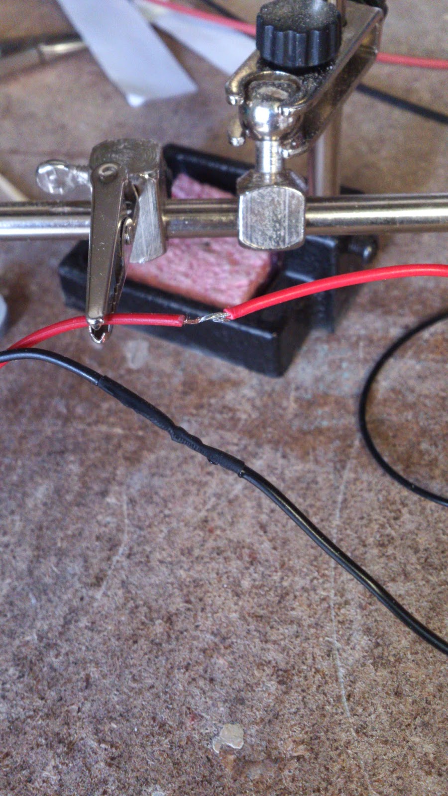
Electronics Assembly - Just soldering up the parts. Attached the buttons and switches. Mounted the LED strips and placed them in their housing. The usual parts are here, with shrink-wrap to cover the wires and the 3D printed parts which I designed to house my switch and button.


Saturday, October 4, 2014

Studio 4 Journal, Week 5

This Week

  • Button Tests
  • CAD Flat Pattern
  • Filling and Sanding Base
  • Project Plan
Button Tests - As far as testing the buttons go, I've 3D printed and made sure that both brightness and power buttons will physically work. The Brightness button went through some pretty major changed from the first attempt. I've ended up using the flexible abilities of the ABS to hold my Alucobond button in place, while still moving enough to engage the button held beneath. The reason for the final design of the brightness button's bracket is because there needs to be adequate clearance for the button to actually move in.

The Power button was pretty much the same as what had been tested before, so the only adjustment was to file away some plastic which was preventing the button from travelling all the way down.


CAD Flat Pattern - After working out the details for mounting the button and switch, I've drawn out a CAD file which has locating holes for the small parts and also details to cut thin flanges out of the Alucobond to cover the edges of material. I will finalise the details of this on Monday. Speaking of which I realised just now I haven't resolved how to mount the power adapter to the arm.


    Filling and Sanding Base - This step is still part way through, thought I've gone with a 3D printed insert and the part is part way through being primed and sanded. The 3D printed part looks like it will serve its purpose quite well. You can see in the photos how I've cut a test piece that clearly shows how the sphere will be supported away from the cement in the base.


    Project Plan - This is the first time I've used a Gantt chart to try and plan and entire project's movements... I know I've missed things but I guess that's the whole point. If I don't know I've forgotten something, I can't possibly remember it.

    I've used a program called GanttProject. Super easy to use.


    Sunday, September 21, 2014

    Studio 4 Journal, Week 3

    This Week
    • Latex Mould Testing
    • MDF Sphere Continued
    • 1:1 Scale Model
    • Light Source Details
    Latex Mould Testing - I had been a little worried about how well the latex will hold the round shape over such a large area. The test involved making a quick mould with a bowling ball which I borrowed from a friend. The ball is a little old and used with some small gouges in it which means I couldn't use it to make my final product with, however is serves well as a test model.

    I attempted to support the latex with some soil I have laying about, which in the end I think was a bad idea. I really should have found some sand. Perhaps I will go for a drive down to the beach and borrow some from the earth. The final result was covered in bumps. I also noted that the finish was not as smooth as the ball. I need to coat the latex with some Vaseline next time.


    MDF Sphere Continued - Once the sphere had been turned to a ball that I was happy with, I put a load of Estapol over it to try seal the end of the MDF a little before going at it with the high build filler primer. I had a go at sanding it to round as best I could to remove the rings that were left behind by the denser areas where the MDF layers were glued together.

    Further along, I had a suggestion from one of my lecturers to use a ring shaped sanding block and roll around the ball to achieve the perfect sphere. I went about cutting out a ring and ended up just using that as a stand. The easiest approach was to cut the abrasive paper in such a way that i could fold it into a cone and roll it around the ball. At this point, I've filled some small gouges and cracks with car bog, sprayed another coat of filler primer and am waiting for it to dry before I sand it down and repeat one last time, just for the best possible finish I can achieve.

    The more time I spend on this, the better my final product will be. Investment.


    1:1 Scale Model - Though this was in week 1, I figure its an important part in explaining the side of the lamp. Its no small thing, and the design has had a few further modifications since. There is also a lack of the piece of cement that would serve as the base.

    The newer version has a slimmer arm with a taper running from the front and back into the centre of the sphere. Also, there is a taper that runs from the top of the lamp, down to the underside.


    Light Source Details - Again, this was determined in week 1, but I've made some further changes. I've added a brightness adjustment button that should fit well into the existing design. The old power connector was a little ugly, so I've purchased a cleaner plug that I will be able to hide in the design much more easily. I cut away the top of a little button that was attacked to the dimmer I had purchased, so I could solder on my own button that have a better tactile feel.

    There is a short video below showing the function of the electronics.


    The next two week are a teaching break, so I wont have access the workshop at Uni. This does however mean I have no restrictions on my time other than eating and sleeping.

    Saturday, September 13, 2014

    Studio 4 Journal, Week 2

    This is the first journal entry which compliments the research and development process of my lamp design. For those who read this that aren't privileged enough to have seen the complete concept, all you need to know is that it involves a cement sphere and an Alucobond arm.

    This week and the weeks leading up have been full of productivity...
    • On/Off Switch
    • MDF Sphere
    • Latex mold Testing
    • 1:1 Scale Drawing
    • Light source soldering

    On/Off Switch - The first iteration for mounting an on off button under the Alucobond was intended to use the plastic within the laminated sheet as a live hinge. I let a fellow student tinker with the sample I had cut, but they poked it too hard and broke the plastic. I took this on board and decided to set the button on its own mechanism. There were also some strength issues with the 3D printed parts.


    So far the switch it mounted sideways with a cam  that allows for a slimmer fit than if the button was butted up against he Alucobond button.( 40mm vs 30mm) There is probably room for even tighter fitting and slimming. There will also need to be some efforts made to cut away excess material. Some adjustments have been made for a tighter track for the button to slide in and deeper travel.


    MDF Sphere - In order to make accurate cement parts, I need a form to cast a mold from. Starting by laminating MDF sheet together I made a 210mm block. The laminating was done ins two parts, which meant that the MDF was able to bulge slightly, which made laminating the two parts together a little tricky. eventually I found some clamps that had enough strength to clothe the gap properly. Before I started on the large sphere, I tried turning a small one on the lathe at home which turned out pretty terrible. Learning what not to do from the smaller attempt, the large sphere turned out quite alright. I've filled some small gouges that appeared after the turning. Currently, I'm waiting for the putty to set fully before I clean up the sphere and go over it one last time to make it as rough as possible. If I deem it to be inadequate, I'll see about getting a new material and using more precise machinery in the workshop at uni.

    This is more or less my method: https://www.youtube.com/watch?v=3lConTQ-cUw
    I'm taking the technique of using the ghost line as a guide, but my lathe has different mounting gear.


    Later Mold Testing - Before I slap a load of latex on my sphere, I though I should test some smaller objects. Also, I've borrowed a blowing ball which is almost the same size and my design to test with.


    1:1 Scale Drawing - I wont upload the drawing here, but after marking out some variation and narrowing down an accurate drawing which explains the size and workings of the lamp, I'm able to start working on getting on electronics under way. In addition to that, I've moves away from the rectilinear style of arm that I originally had, moving to something with a little more angular style to suite lamp's protruding angles.

    Light Source Soldering - The lighting is provided by 9 strips of LEDs that are each 15mm long. Initially I had considered a brightness adjustment, but moved away from it because of the complexity of circuitry, but since that decision I've realised I might be able to wire in a dimming button with little effort. Possibly looking at using some Acrylic as a diffuser, but it might block too much light and i will need to do some testing.