Hello and Welcome!

Hello and Welcome!

My name is John Nicholl. I'm an Industrial Design student, based in Adelaide, South Australia and this is the beginning of somewhere that I can think aloud and share my work.

This blog is somewhat outdated.
More current projects are posted on my website.

Twitter, Instagram and Tumblr: jwrnicholl

Friday, May 30, 2014

Computer Modelling Journal, Week 11

Final Week!

This weeks has bee super busy. I'm mentally exhausted. The finishing touches to the model this week involved a lot of tiny little bosses and cuts to create the important clips for the inside of the mouse. (which by the way is terrible and has excruciatingly low tracking resolution)

Some fine wires to make contact with the battery have been added to the PCB assembly. Their construction is quite simple. A few sketches to use as construction for a sweep feature. Some techniques that I've not used in Solidworks before were the helix and coil tools. Very interesting.


Holes and details to the gray middle area have been added. Some of the features have been simplified, simply because of time constraints. I have no doubt I could recreate them in any other case.


Some issues revealed themselves when dealing with the bottom section of the mouse. One was a self intersection error when trying to thicken the surfaces I'd modeled. Another was zero thickness geometry  when i tried a different approach to creating the part. Ultimately I gave up on it, but the part looks accurate enough in my opinion. The following image is the oversize thickness that was created with another approach. I trashed that.


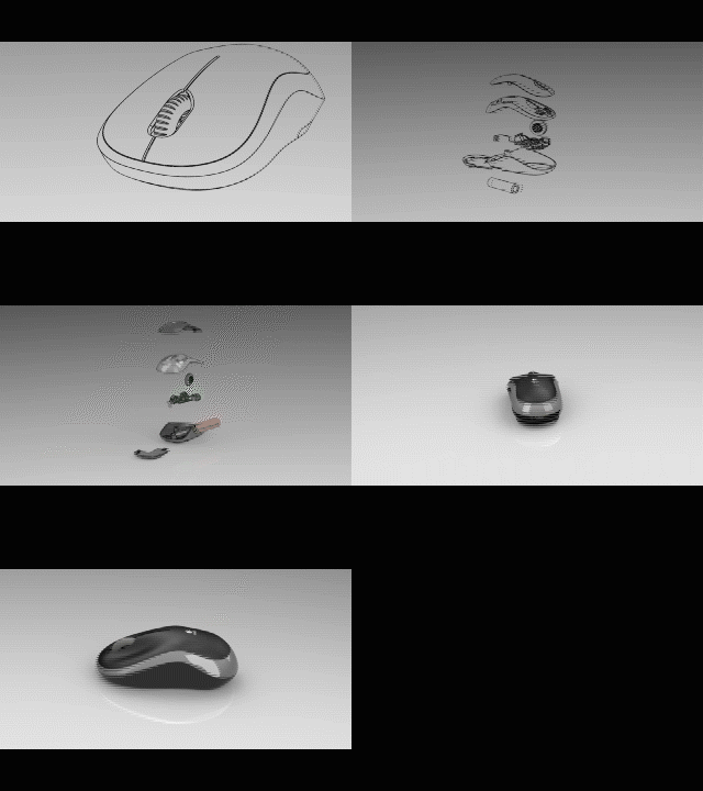
Moving on to creating renders and animations... I had a frustrating time, leaving my motion study render running for a whole 2 days, then realising it. glitches out and all my camera angles were snapping isntead of transitioning smoothly. Don't know why, but it worked the second time around when i toned down the render quality. I used some editing software to transition from a line drawing to a fully rendered animation just for the hell of it. Still photo renders were not a hassle, although the Photoview feature which rounds off sharp edges couldn't figure out how to make it work for the organic curves of the mouse. Point is I know its there and the software is just not quite smart enough. Here's a gif of my animation and some comparisons between rounded edges on a part.


All in all I'm happy with the result. I didn't feel as though much needed to be adjusted to the scene for the renders. I believe there is a reason the defaults are set the way they are, thought i did play around for a while before coming to this conclusion.


Finished Renders!


Saturday, May 24, 2014

Computer Modelling Journal, Week 10

This week has been slow, but so far the PCB and components are finished to a level that I'm satisfied with.


Some progress on the Mouse's outer parts has been made also. Mostly with regards to the gray strip that runs around the edge of the mouse and houses the top part. So far it has thickness and some progress towards adding the small lip that exists around its edge has been made. This week hasn't been one for progress. Hopefully the next will be.


Sunday, May 18, 2014

Computer Modelling Journal, Week 8

This week I've started to focus on the overall body of the mouse. Using some tools that I've not used before. These are the surface tools in Solidworks, which allow for the creation of faces with no mass.

The approach so far has been to create completely curved surfaces from traced splines. The first step was laying out photographs of the mouse which were taken from a fair distance to reduce any perspective distortion. I used a camera with a 50x zoom lens which I borrowed. It worked a treat I Think. Once they were imported into Solidworks I began tracing important features

First up was the gray area through the centre, just because it looks fun. I started with a couple of splines that follow the side profile of the gray band, then followed with outlines from the top view and also the bottom. The bottom outline is just the overall outline of the mouse.


Using the outlines and the profile lines, I projected curves in 3D space that could then be used as surface loft guides. There are also some splines which arm from the top and bottom of the gray band which serve as the loft's profile.

The bottom chamfer of the mouse was next up. This way I could use the top and bottom curves of the chamfer and gray bands respectively to create the middle section. The same process is repeated through the rest of the model as it stands for now.

This is the middle section...

To evaluate my model, I've used the Curvature and Zebra Stripes tools. The Curvature tool shows the rate at which curves change. If the colours indicate a smooth transition between curves, the part will look sleek, if not it will look like a boring bunch of polygons. The Zebra Stripes tool shows how the light would reflect around the object. Very fun to play with.


Finally, just because renders are fun, this is what it looks like so far...


Computer Modelling Journal, Week 9

This week I filled in the top and trimmed out the battery cover. The top piece is a filled surface with three guides that all have equal curvature to the band that runs around the mouse. The construction for these lines was a little bit of a pain, because Solidworks doesn't like cooperating with me. The guides had to be contained to projected curves that run along the sides of the mouse.


You'll notice the finger indents are already there. Those were made with the Freeform tool. Symmetry is important for this one. I trued to minimise the amount of movement to achieve the right shape. Too much movement distorts other pants of the surface.


The approach  for making two separate surfaces bodies for the battery cover and bottom parts the base has to be duplicated, then trimmed so that there are two surface bodies which are identical to what existed previously. A series of projected curves and sketches  were used to create a compound curve that i could use to trim the surface bodies.


I've had a play with the middle piece's recess for when I start adding thickness to the parts. Using a simple offset surface from the top piece works well, but it doesn't accurately represent the front of the recess where it is slightly larger and has a steeper angle that the rear. I'm going to have a thing about this one.


Friday, May 2, 2014

Computer Modelling Journal, Week 7

Over the break I've been focusing on things other than CAD and Solidworks, Some efforts to model up the PCB. I don't think it's at a stage that I'm happy with. It would be nice to build up a few more components so it really does represent what actually exists more closely.

The approach was to use a photo of the board as a guide for the overall shape, then just use the vernier callipers to pull more accurate dimensions. The chances are I'll have to adjust the board slightly later on once I've build the main body pieces that it sits inside.


I've detached the tracking sensor and the plastic reflector piece from the board. and hopefully i'll be able to model up the wires which span from the board to it.


I'll have to model up the sensor too, and house it in the slot there at the back of the board. So far it looks all right. I don't like the colour though. There isn't a style that already exists for the PCB in Solidworks, I'll have to try making a custom one, if not just stick with a single colour and hopefully the details will do it justice.