Modelling the Logitech M185 Wireless Mouse.
Looking at the mouse, its got a really organic shape. It'd going to take a lot more effort that the previous project. The focus is to learn how to use Solidworks' "Surface" tools which apparently make modelling these fluid shapes much easier.


Before getting into too much detail, there are three parts that can just pull apart on the mouse, excluding the battery. Mouse, Bottom cover and USB Receiver. I'll be modelling the receiver also.

Here's the breakdown into the three main assemblies that will exist. There's the Base and Top sections. The top consists of the two left most parts, and the bottom on the right. Within these there are smaller parts... like the scroll wheel mechanism in the top and the electronics in the bottom. I'll probably end up with some sub-assemblies in the larger bottom part.

Until I've had a chance to learn more about using those tools, I'm going to focus on the parts which i can model easily and save myself time further down the track. So that means i'll start with the scroll wheel and the spring that makes it click. Quite a simple mechanism inside. It'd be interesting to see the workings of the Logitech mice which have the "Hyper-Fast Scrolling" feature which allows switching between standard clicking and a freely spinning wheel.


There will be three parts to the mechanism that I can make right now... but the larger middle section of the mouse will have to wait. There some heavy stuff going on there. You haven't seen the underside of it yet. The frustrating part of this project is that making the mouse from scratch with a self created design in mind would be simple enough, but trying to derive dimensions from an organic shape like it is will be difficult. I've considered encasing the whole mouse in a resin and then cutting it into sections with a band saw... but I'm not sure if it will get clear enough information to work with, especially if i don't know how far from the edges of the mouse I actually am. A clear resin might do the trick though. Oops, tangent.

So I've forgotten to measure the inside of the rubber part, and subsequently the thickness of the outer ring of the inner part of the wheel. 14.7 mm on the inside of the plastic innards and 15 on its outside. Therefore 15 also for the rubber.
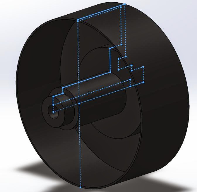
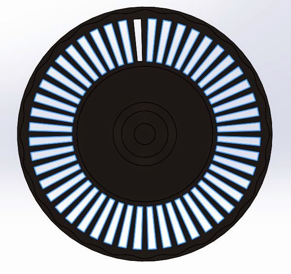
The basic approach was to make the inner section of the wheel first. Pretty simple with a revolve from a sketch with all the necessary dimensions. I noticed there was some additional thickness in a rippling form on the inside of the wheel, so I added that in before cutting away the holes to make the botches which cause that awesome click sound when you scroll.


Making the rubber outside of the wheel probably could have been approached differently, but what I've got looks pretty accurate to me. First came a revolve with a parabola. Then a boundary cut between a sketch on a plane above the wheel and another on the front plane. Repeating the same cut gave the other half of the groove. (Errors occurred with a mirror feature) Finally, a 1 mm fillet finished the wheel.


Smack the two together in an assembly, and there it is.


