The latest finished project of mine is a stool which was made for a furniture design course. The brief was to use an existing piece of furniture from a shortlist and use it as the inspiration for a design.
The inspiration I chose was a bench by Jon Goulder called LEDA seat. I chose to replicate the style of the seat in my own stool design with what tools were available to me. The slats are CNC machined high quality plywood and the legs are made from laser cut mild steel.
Currently it sits as a bedside table that i pull out on occasion as an extra seat if I've got a guest that needs to sit at my desk beside me. Having a blanket folded up an inserted into a cushion cover resting on the top of the stool makes for a great place to drop a phone onto after a long day and soothes the butt cheeks when you sit on it.
The final grade I received for this project was well below what i was expecting, especially considering the hours of designing and modelling to make sure that the curves would all align and the piece could be assembled in the real world, not just a CAD environment. I wouldn't say I'm a fan of the design wank that a lot of people seem to push these days, but I appreciate the artistic aspect of design. This piece is fairly far from the functional and simple form of design that I would prefer but its nice to try something different for a change.
A Product Design Journey
The progression of my exploration into the realm of Industrial Design
Hello and Welcome!
Hello and Welcome!
My name is John Nicholl. I'm an Industrial Design student, based in Adelaide, South Australia and this is the beginning of somewhere that I can think aloud and share my work.
More current projects are posted on my website.
Twitter, Instagram and Tumblr: jwrnicholl
Thursday, July 16, 2015
Monday, October 27, 2014
Studio 4 Journal, Week 8
This Week
New Top Sphere Attempt - I'm not happy with the way the first top piece turned out, so I figured i should attempt to cast the part using plaster as the mould. The first step was to use the MDF sphere's bottom half to create the domed mold. The plan was to use this dome, place the top part of the MDF sphere in the dome and pour plaster into the empty space where the housing is. Finally, removing the parts and plaster insert from the dome would leave me with the right parts to cast a new top part. The plan fell apart when I could not remove the plaster from the housing section. Otherwise, I think this would have worked.
- New Base
- New Top Sphere Attempt
- Assembly
- Design Refinement
New Base - The previous base was too small to support the weight of the arm without rolling out of the ring. A larger ring of contact was needed, and so I turned a mould to cast in which supports the lamp. I used timber to create the mould, then sealed it with Cabothane and coated it with Vaseline to keen teh cement from bonding to the timber. The bolt helped remove the casting from the mould.
New Top Sphere Attempt - I'm not happy with the way the first top piece turned out, so I figured i should attempt to cast the part using plaster as the mould. The first step was to use the MDF sphere's bottom half to create the domed mold. The plan was to use this dome, place the top part of the MDF sphere in the dome and pour plaster into the empty space where the housing is. Finally, removing the parts and plaster insert from the dome would leave me with the right parts to cast a new top part. The plan fell apart when I could not remove the plaster from the housing section. Otherwise, I think this would have worked.
Assembly - With all the parts finally cast and ready, I drilled the holes with a masonry bit into both sides of the sphere, mixed some Araldite and assembled the two halves around the arm with threaded rod.
Design Refinement - After consideration and time to brainstorm, I've come up with some alternative solutions. The most pressing issue is balancing the arm. Different materials could solve this. Also a more foxed base solution.
Saturday, October 18, 2014
Studio 4 Journal, Week 7
This Week:
- Chiseling the Sphere
- Latex Moulds
- Cement Pouring
- Electronics Assembly
Chiseling the Sphere - Forming an angle is the most complex step to this part. I decided to use a chisel to achieve this, simply because it would take just as long as setting up a machine to do so.
Latex Moulds - I went through and covered the rest of the parts in latex. For the top part of the sphere, I needed to coat inside of the channel and also, the outside. I made up some boxes to pour plaster in, then press the latex mould in with the MDF parts to support them. this way when I removed the MDF parts, the latex will be supported for pouring cement.
Cement Pouring - Pouring the cement went well. I'm not so sure about the mould that I made for the top part of the sphere. Time will tell how well it has turned out.
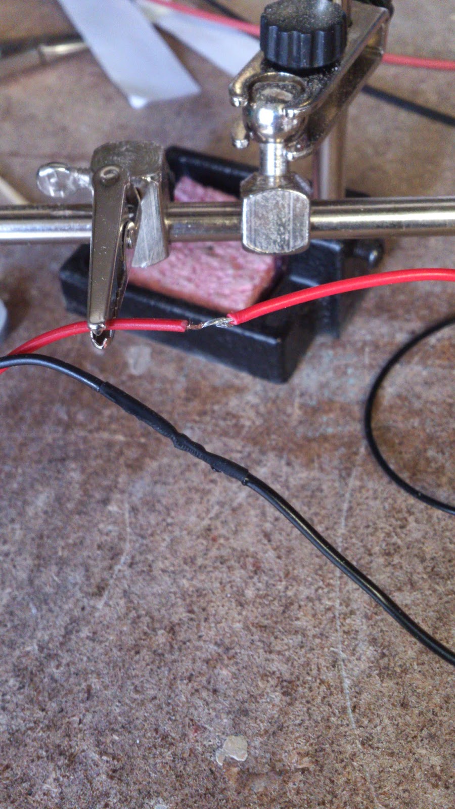
Electronics Assembly - Just soldering up the parts. Attached the buttons and switches. Mounted the LED strips and placed them in their housing. The usual parts are here, with shrink-wrap to cover the wires and the 3D printed parts which I designed to house my switch and button.
Saturday, October 11, 2014
Studio 4 Journal, Week 6
This Week
- Cutting the Sphere
- Preparing and CNC Cutting
- Folding and Bending Alucobond
- Milling the Sphere
- Polish and Latex the Sphere
Cutting the Sphere - We decided that the best way to cut the sphere would be to rig it up in something to fasten it as best we could, then run it though the band saw. The recording of the cutting as too long to upload, but here is the setup we used and photos of the results.
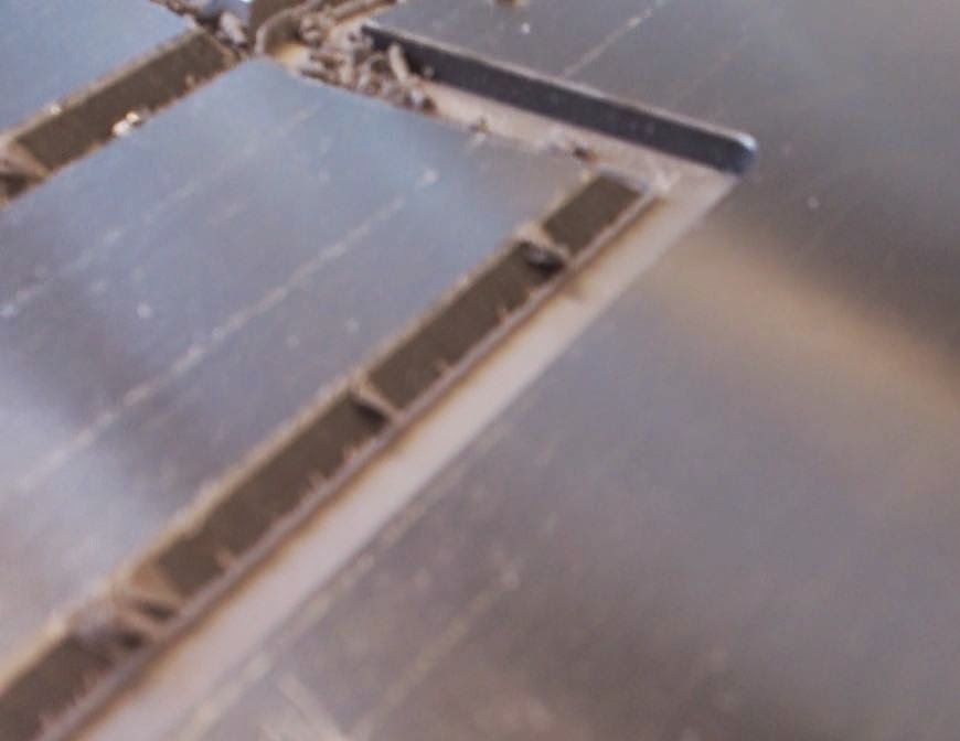
Preparing and CNC Cutting - It doesn't take much to get the Alucobond cut, once the prep work is done.Working from the CAD model I made earlier made it easy to draw up a sketch over the flat pattern and drop in some lines which could be used as a path for the milling machine to follow.. The most complex part was getting,
Folding and Bending Alucobond - Once all the cutting was complete, I separated each part from the sheet by cutting the bridges that are left behind to make sure the parts don't move while cutting is still happening. Folding along the corners was easy, however folding the edges that covered the ends of the sheet was not. I used a mallet, clamps and a piece of scrap material to beat the thin aluminium around to cover the ends of the sheet. Once all teh folding was complete, I also used araldite to adheer some small brackets that I'd 3D printed to keep the folds at a consistent angle.
Milling the Sphere - After I cut the sphere and folded the Alucobond, I was able to take accurate measurements of the Alucobond and transfer them over to the smaller segment of the sphere's inside face, ready to be cut. The technique was easy enough. Back and forth, while only ever entering a cut from the outside, never breaking through the surface of the sphere from the inside to avoid chipping the finish. The next step is to chisel out the remaining material which is left in the middle. I chose not to use the milling machine to cut any angular paths, simply because it would likely take just as long as doing it by hand and I don't have access to the workshop all the time. I also have to chisel in the angle which will be visible to the outside edge that contacts the sphere.
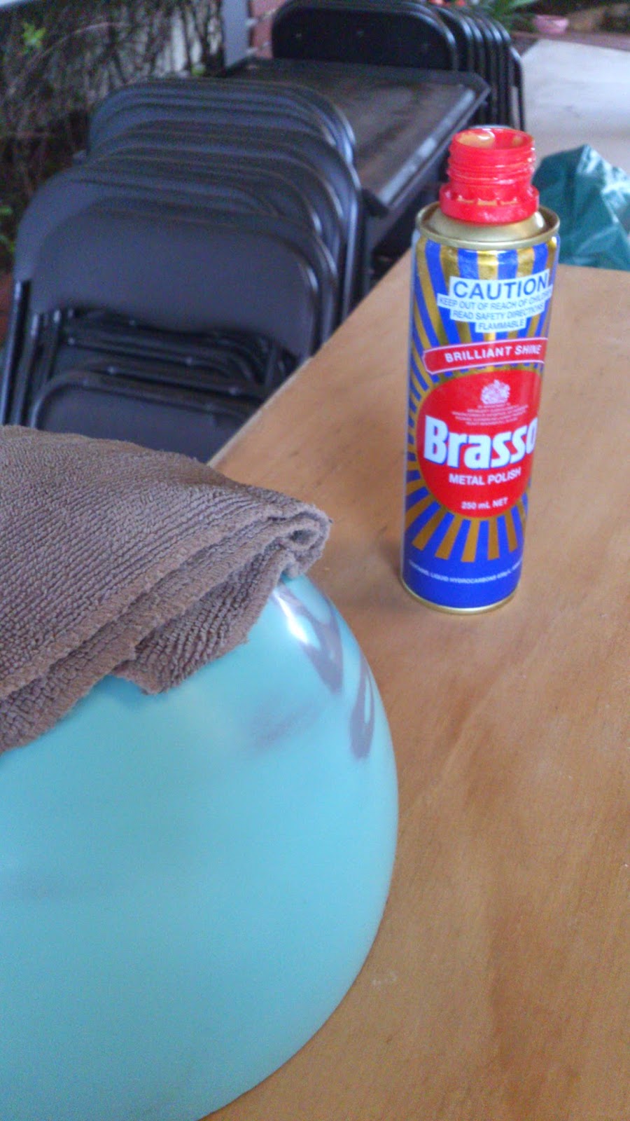
Polish and Latex the Sphere - Also this week, I used a cut polish to shine up the larger portion of the sphere and started coating it in latex to make my mold. I managed to get it to a finish that looked like a bowling ball. Hopefully the surface finish will carry through my latex and into the cement when I cast it. I tried to show the shine clearly in the last image. Look for the reflection of the brasso bottle.
Subscribe to:
Comments (Atom)


